|
| |
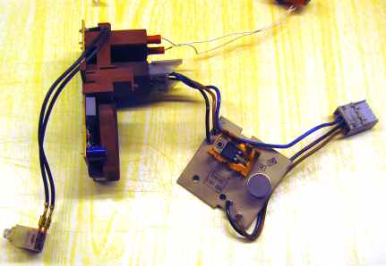
Miele S591 Vacuum Cleaner RepairTim describes how he repaired his Miele S591 vacuum cleaner, via a series of emails, as follows. The vacuum cleaner is a Miele S591, and I have replaced the bearings three times. The motor seems to be OK just now. The brushes are certainly OK. As I said, the cleaner seems to hunt when on an intermediate speed setting. On max it uses 1400w which is a bit OTT and so we usually use it slowed down using the knob which adjusts the speed by way of a plastic shaft into a potentiometer on the control PCB. When its on max, or min speed it works fine but not when on an intermediate speed. So, I have removed the PCBs and connected them up with mains on the input and a 100w bulb on the output. When turned on the bulb glows gently at the lowest setting and brightly at the highest setting but when on halfway it flickers with a frequency of maybe 0.5HZ. The motor when it hunts speeds up and slows down with a period of probably 4 seconds. So, attached are pictures of the PCBs. | |
|
| |
| There are 2 PCBs. One is normally fitted in clean air, uncooled, and one in dirty air cooled. The one in dirty air has the TRIAC which probably needs forced air cooling. | |
|
| |
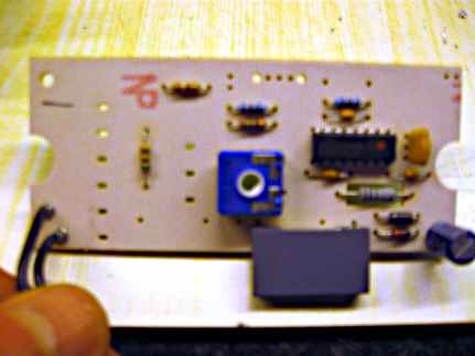
| So I removed the control board from its plastic mounting and plugs in order to draw a circuit diagram. When I investigated the controller chip which is an ST 8 bit microcontroller I discovered that ST had already drawn a sample circuit which was very similar to mine and so I printed it and modified it. I have scanned the result and attached it. I have attached the pdf from ST which says how their proforma circuit works. There is one bit missing from the diagram. There is a capacitor with three legs on the front of the motor. This is connected to the two leads to the motor and also a third lead which runs from the gate connection on the TRIAC. It may be unimportant, or not! So, I think the microcontroller is working and managing the TRIAC. But it is varying the speed in an odd way. There is a feedback circuit from the gate into a connection on the microcontroller, but what its measuring and at what point in the mains waveform cycle I have no idea. You suggested I could replace a component or components but none of them look faulty or damaged. I will carry on messing about with this to see if I can fix it. Any ideas would be welcome. __ I disassembled the motor again to retrieve the capacitor that I mentioned before. It wasn't what I thought. The capacitor is sited as near to the motor connections as they could put it, and it's connected across mains live and neutral only. So there is an extra live wire from just before the TRIAC down to the motor but only connecting to this cap. It's an X2 275v 0.22uF, so that's standard interference suppression or phase angle correction. I have added it to my test circuit with the 100W light bulb but it made no difference to behaviour, as it's just across the mains anyway. I have measured the DC voltage on the 25v cap and its about 4.1v. It doesn't change much or do anything odd when altering the pot to change the output voltage to the light bulb. I have ordered a replacement TRIAC (well 5 of from RS for £1.68 including postage next day courier, I don't know why RS Components company give me this service but I don't mind). I will fit that next. Oh, while I had the motor apart I measured the resistance between each of the adjacent commutator segments and they were all the same. And the field windings matched one another. So I don't think there is a problem there. __ I measured the speed control potentiometer as best I could, given that it is still in the circuit. The ends of the pot (Vss and Vdd) were effectively shorted by the rest of the circuit relative to the meter scale I was using. The centre connection read about 60K, gradually reducing to very little at either end and I took that to be reasonable behaviour. Its an ACP pot and there are similar ones on ebay (blue squares with a white centre for turning with a screwdriver) but they don't have the wires in the same place (for lie flat mounting) and they would not accommodate the operating shaft without modification. I have not found one the same as mine. __ So, I replaced the TRIAC. This altered the behaviour, I think because the new TRIAC was responding slightly differently to gate current, but the circuit was still misbehaving. So I rebuilt the cleaner and the motor was hunting more or less as before. So I removed the 220uF 25v on the control board power supply and fitted a 100uF 25v which I happened to have. The behaviour changed markedly, rather for the worse, with the motor unable to reach full speed and the speed variation being much worse. So the value and behaviour of this component looks important. So I removed that and fitted (very badly because it's totally the wrong size) a 470uF 16v. That supercharged the motor speed and fixed the behaviour. However the motor ran at max speed for much of the potentiometer adjustment range and only maybe half speed at minimum. The DC voltage reading on the capacitor (and so to all of the control circuit) was 4.9v. It was 4.1v with the 220uF. So, maybe I have to replace the 220uF and the Zener diode. The 100 ohm resistor reads 101 ohms and looks OK. Maybe the 0.22 275v cap is dodgy. __ The 100nf capacitors are actually 100nf - well they are marked '104' which is I think 100nf. However I don't know if they are ceramic or polyester. They are small round items, wire ended, but not in any sense flat or standing up. If I replace them, which would be better, ceramic or polyester, given that they seem to be noise reduction/decoupling around an I.C? They are easy enough to replace and don't cost anything worth talking about. __ Link for the capacitors. Two of them are 100nF 50V +-20% codes: https://www.avx.com/products/ceramic-capacitors/leaded/sa-series/ A5E104 MC1317 and A5E104 MAX317. They were made in Week 17 of 2003. The third is 1nF code: 102KC1 11C323. I haven't decoded this yet. __ They are radial lead MLCs and you might be able to determine the voltage rating from the circuit position. C4, for example, it connected to the IC so it won't see more than the chip's supply voltage. Likewise, C1 is across the zener. One thing I forgot to mention is the PCB. A cracked track or pad can cause weird symptoms. Inspect carefully. __ So, I replaced all of the components in the power supply. That was:
At the same time I replaced
When I powered it up on the bench, the dc voltage came up at 5.6v. Well that was different because before it was 4.1v which made no sense in relation to the zener voltage, supposedly 6.2v. On the other hand, 5.6v is about one diode junction (the 1N4007) less than 6.2v, so that looks better. So I put it together, and it works fine. And I have just cleaned the downstairs carpets with it. So not only did we avoid paying for a new vacuum cleaner, we avoided throwing away a very large piece of plastic casing into the environment only to buy another one.
| |
| Send this page address - CLICK HERE - to a friend ! | |