| | Fitting an MGB-GT gearbox to an Austin A40 (or similar) There is nothing all that unusual about an Austin A40 fitted with a 1275 engine, not even a tuned one. And Martin Pickering is probably not the very first person to fit a Ford rear axle to a BMC car in search of stronger half-shafts. Sprite front discs and a servo aren't going to blow anyone's mind. But an A-series engine fitted with a MGB all-synchro gearbox - now that's beginning to sound interesting.
Why you may ask, would anyone went to fit a 'B' box to an A-series engine? Well, it is a lot stronger then even the Spridget item; from 1970 onwards it has synchromesh on all four forward gears and, best of all, it is available with overdrive.
This whole business of fitting nonstandard gearboxes to engines not designed for them is well worth investigating, and, if nothing else, the story of how Martin did his conversion gives a very good idea of what is involved in such an undertaking. The box was the later all-synchro type which is also a lot stronger.
| 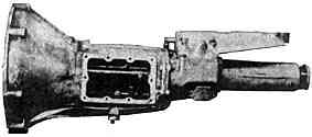
| MGB-GT gearbox (non-overdrive).
The overdrive version is slightly longer. |
FACILITIES
First and foremost, you are going to need a lot of elbow grease, if you want to keep expenses to a minimum. Even so, there is a number of jobs which will have to be done in a machine shop and, if you do not have free access to one, you will have to pay an engineer to do the jobs for you. This should not be too expensive if you provide him with all the information in this article.
ADAPTOR PLATE
This is the heart of the conversion. You will need 3/8" mild steel plate, of a minimum size of 13.75 " square. Accurate alignment is vital and the crucial dimensions are all shown in the drawing. The very light black lines show the outline of the original A-series backplate and this is used as a jig to drill & cut all the holes relating to the A-series block and also for locating the crank centre line (which is NOT necessarily concentric with the centre of the semi-circle in the hole in the middle). The position of said crank centre is found by its distance from the two plate-to-block dowel holes as shown marked 'D'. The old plate is used as a jig to drill and then ream these holes into a new plate and then the old plate is dowelled to the new one. It can then be used as a jig to drill all the plate-to-block bolt holes into the new plate and also to mark out the size and shape of the oil-pump and main bearing housing holes - these two holes varying slightly according to the exact engine. The position of the starter motor hole depends on the flywheel.
| 
| From the crank centre, which has been located relative to dowel holes 'D', the positions of the gearbox fixing holes can be marked out. All except hole 'Y' are on a circle of radius 6.875" from the crank centre. Those marked 'Z' should be drilled to 3/8" with a generous clearance, likewise 'Y', whilst the two holes 'X' are tapped to 5/16" UNC to take a pair of rocker box studs, as there is no room for bolt heads between block and plate. Similarly, starter motor holes (which are 5-inches apart) are tapped 3/8" UNF so the locating bolts screw directly into the plate. This is because the holes fall within the bounds of the bellhousing. |
| 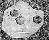
| The heavy black line in the sketch represents the approximate shape that the plate should end up at, though the photo (left) shows an 'optional' extra lump to fully blank off the starter motor hole in the bellhousing. Large holes for starter, oil pump and centre could be cut out by a man with a cutting torch and filed smooth to finish, or drilled all round the outline, chiselled out, and again filed to finish. All dimensions should have been marked out carefully before any cutting is undertaken. The finished plate may need cropping in some spots to clear things like exhausts, bodywork, steering etc. again depending on the exact car its all fitted to. |
FLYWHEEL
This is where things get quite tricky. When the conversion was first done, it was on a 948 engine, with a 1098 flywheel and clutch cover. (The radius, from the crank centre, of the centre of the starter hole is thus 5.6875 inches.) A special clutch plate was obtained from Automotive Products, of 7.25 -inch diameter as per A40, but with 1-inch-diameter/23-splines centre to suit the MGB input shaft. This is part number CP2257-9, and 7.25-inch diameter should be specified. An alternative, if you hire AP's drilling jig, is to drill for the different dowel positions to fit a special AP 7.5-inch diaphragm clutch cover and 7.5-inch version of aforementioned plate. The diaphragm cover is part no. CP2257-5. When the 1275 engine was fitted (which came from a Spridget, not Marina), extra bolt holes were drilled onto the 1098 flywheel to fit it to the 1275 engine. This is necessary as the smaller engines have 4-bolt flywheel attachment, 1275s are six-bolt.
All was not well with this set-up: the clutch kept breaking because the original adaptor plate was not properly aligned. The final solution was to make up the plate as shown in the diagram, and use a 1.3 Marina flywheel. Strangely enough, although this flywheel has the advantage that a standard MGB clutch assembly goes straight on, it has the disadvantage that it does not go straight onto the 1275 Sprite crank. This is because the Marina 1.3 engine has a larger crank flange than the 1275 Spridget engine and it has only one dowel: the Sprite has two dowels, one of which is offset.
| 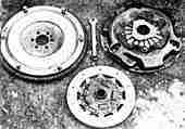
| What Martin did was to remove the offset dowel from the Sprite crank. The flywheel was then bolted up and centred by turning the crank on Vee-blocks and using a dial gauge to check on run-out, Once this was as good as it could be, he drilled through flywheel and crank and reamed out to 3/8" to take a new locating dowel. A more satisfactory alternative, if you have the crank out of the car, is to have a machine-shop sleeve down the recess in the Marina flywheel to be a perfect fit on the Sprite crank. The offset dowel would still have to be removed from the latter. |
Obviously if you are fitting the Marina flywheel to a Marina engine, none of the problems would have arisen. On the 1275 Spridget, yet another alternative would be to use a Marina crank, with the big-ends turned down to suit the smaller Sprite con-rod big-ends. (An advantage of this method is that you can offset-grind the large big-ends to give a longer stroke, thus increasing the engine capacity. Don't forget to skim an appropriate amount off the piston crowns!)
The Marina flywheel should be the later type for the 8-inch clutch, so that the MGB clutch assembly can go straight on. Also, with the Marina flywheel the starter motor must be positioned further out from the crank centre, on a radius of 6.3125 inches.
| 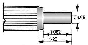
| On all engines, with the possible exception of the 1.3 Marina, the crankshaft spigot bush is of 1/2-inch diameter, and the MGB input shaft has to be shortened and turned down to fit. The drawing shows the dimensions. The length of the spigot shaft is shown from the end of the splines, which are unaltered. This mod was done on a crank grinding machine and cost Martin 4.50 (in 1975). |
Also, in all cases, you will need to juggle about with the length of the clutch release pushrod. The one in the drawing was from a Mini and the length shown is for the Marina flywheel/MGB clutch and release arm combination.
The MGB clutch slave cylinder was retained, with the MGB end of the pipe brazed to the A40 pipe as the respective unions are of different dimensions. Initially the A40 master cylinder was used but the clutch was very heavy and it barely released with the pedal on the floor. A change to an Austin 1100 master cylinder with a smaller bore and longer travel gave much more satisfactory results.
One important point was the need to bash a hole in the bellhousing to clear the starter dog. A nicer but more expensive solution would be to reverse the flywheel ring gear and use a pre-engaged starter from Marina 1.8 or MGB.
| 
| The sketch shows the length of the propshaft on Martin's set-up, with non-overdrive gearbox and Anglia rear axle. The MGB splined end is welded to the remainder of propshaft to suit whatever axle you have. Some lee-way is allowable as it can be accommodated by said splines. | | 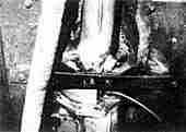
| The gearbox crossmember is largely self-explanatory from the drawing and photograph. Use a couple of plates where it bolts to the floor in order to spread the load. | | 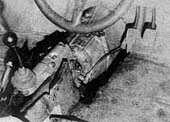
| On the A40 the gearbox tunnel was chopped out and rebuilt, The gearstick ended up more or less in line with the front supports of the seats, Don't forget to allow a hole for the gearbox filler plug, Minor handbrake alterations may be needed, dependent on the car and how you rebuild the transmission tunnel. Speedometer cable was A35 van as this had adequate length and the right head to suit the A40 speedo. |
There you have it; the story of how a better gearbox was fitted to one man's car. Whether you fancy this particular conversion for your own car, or some other combination of engine and box, I hope that the sort of problems Martin came across, and the way he tackled them, will be of interest and use, whatever car you are modifying.
Jeremy Sinek
HOTCAR magazine, June 1976. | |