| | Back to index page Send this page address - CLICK HERE - to a friend ! How to Solder and desolder with an iron
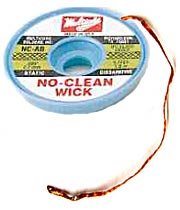 Multicore desolder wick®
The desoldering braid or "Multicore desolder wick®" has a limited shelf life - after a few weeks it begins to oxidise. Keep it in the bag until you want to use it.
The purpose of the Multicore desolder wick® is to remove solder from a soldered joint to leave the component lead completely free and loose. You can achieve this result quite easily but it does take a little practice! If you have a scrap printed circuit board then please practise on that first. Switch on your soldering iron and let it heat up.
As a beginner, you will find it helpful to "tin" the wick with solder. Unwind at least 100mm of wick from the reel and place the end on a hard surface that will withstand the heat of your soldering iron tip - a piece of wood or something that doesn't matter.
This is your work surface.
| Dear Sir, Thank you for the prompt despatch of the Solder Kit. The information contained within the kit (you are reading it) proved to be very useful as I have not had much success with desoldering using copper braid before. H Carrier ESq. |
Hold the soldering iron in your dominant hand and hold the solder with the other.
Press the soldering iron tip down on the wick, near the end, and push the end of the solder wire so that it touches the wick and the tip of the iron. Twist the iron in your hand so that the tip rotates slightly back and forth. This has the effect of improving the heat-connection with the wick, of rubbing away oxides as they form and of encouraging the solder to flow around the iron tip. Bear in mind that the object of this exercise is to apply a little solder to the end of the wick. I stress "a little"!
Now get the printed circuit board assembly and turn it upside down. Select the joint to be desoldered. You can mark it with an indelible pen to make it easier to recognise. Place the Multicore desolder wick® across the solder joint so that the part which you soldered is adjacent to the joint but a fresh section of wick is actually across the solder joint.
Press the side of the iron tip onto the soldered part of the wick then roll the tip back onto the solder joint. The idea is this: The solder you have put onto the wick will melt and this helps the iron to transfer heat rapidly into the wick. It provides a "good thermal connection" immediately. You roll the iron tip along the wick onto the fresh section, which lies across the solder joint, and the heat already in the wick, plus fresh heat from the iron tip, melts the solder joint so the wick can "soak it up" by capillary action. It is important to maintain a steady downward pressure with the iron tip until all the solder has been soaked away from the joint. If some solder still remains, move the wick so a fresh section lies over the remaining solder and press the iron down on it again. You don't need to use excessive force. If the solder does not melt within one second then you do not have a good thermal contact - apply fresh solder to the joint then try again.
Once all the solder has been removed you should be able to lift the component wire out of the hole without damaging the copper track or pad.
Sometimes the component wire is bent down onto the track, in which case tugging at the component can tear the track. In such a case you can often use side-cutters to cut away the component leg close to the top surface of the printed circuit board. The remaining leg wire can then be pushed away by careful use of the soldering iron.
| 
| Electronics tutorial for beginners Easier to understand than anything you've read previously! Martin has a knack of explaining technical subjects in simple language. Components covered include resistors, diodes, transistors and capacitors. This is NOT just another boring technical book full of mathematical equations. You'll like it! |
Some PCBs (e.g. Churchill) use "plated-through holes" where the copper pad goes all the way through the board. To remove the solder from these you can use the same technique but first add a little fresh solder to the component joint before applying the Multicore desolder wick®.
One of the problems you will encounter is that the application of excess pressure or heat for too long a time can break the glue bond between pad and board. With practice, this effect can usually be avoided but even experts cause damage occasionally. If damage occurs, you must repair it with the wire provided. This wire is coated with Teflon which does not melt. Use a sharp blade to scrape the green epoxy coating off the remaining track for 3 to 5mm. Apply solder to "tin" the track. Strip 3mm of insulation from the wire and solder the end to the exposed copper track. Strip 10mm of insulation from the wire and wrap it around the component leg to form a new solder pad. Solder the joint.
In some cases it it easier to solder the wire to the nearest pad which is connected to the damaged track. Often, the wire required is so short that you will not need any insulation, in which case simply strip 30 - 40mm and use the bare wire. Although the instructions, above, suggest stripping the wire after soldering one end to the track, in practice you will cause more damage by doing this so, as a novice, strip the insulation before attempting to solder the wire. | 
| A Beginner's Guide to Receiver Repair Based on the original "Screwdriver Expert's Guide to Satellite Receivers" this book describes the basic components and a typical power supply with diagrams and explanations. Shows how to solder and describes what to check and measure. It won't make you an expert but, if you are capable of soldering in components supplied as a kit, it will take you one step further so you understand why you are doing it and even help you figure out other possible fault causes and cures. If you buy a repair kit, you need this book. I guarantee you'll be delighted with this amazing book full of information! |
Soldering is generally easier than desoldering but still needs practice.
Keep the soldering iron tip clean with a damp sponge and tin it with fresh solder before use. Wipe off excess solder on the sponge. Never use the iron to "carry solder to the joint."
Estimate the distance between the holes and bend the component wires to match. Test the component wire pitch by fitting the component through the board from the rear. Once it is correct, fit the component from the top side of the board, pushing it down gently until it reaches the board or, in the case of a capacitor where the lead pitch is often incorrect, until the capacitor sits with the wires bent at no more than 45 degree angle.
| 
| Larger components should be pressed firmly down to the board. Once the component is seated, bend the wires beneath the board in the direction of the connecting track if possible. A 45 degree bend is adequate. Solder the joints by pressing the iron tip against the wire and the copper pad and applying solder to both. Rotate the iron tip back and forth to assist heat conduction, cleaning and solder flow. <-- This is how NOT to mount it! There should be no gap. (Except with smaller parts where the wires are closer together than the hole pitch.) | | 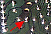
| Finally, use sharp side-cutters to crop the excess wire 1mm above the solder joint. If the component is not seated then the result is likely to be a solder pad which cracks away from its track. |
Safety First
Heat is the most obvious danger. Solder starts to melt at around 250 C but the iron tip needs to be hotter than this to ensure a good flow of solder. Special holsters or rests with safety guards are available for soldering irons and these should be used.
Keep children out of the room while the soldering iron is hot. Don't wear your best clothes because you may burn the material or splash molten solder on it. If you don't wear spectacles then eye protection is strongly recommended.
If you do burn yourself, get the affected part immediately under cold, running water. Plunging it into a jug of cold water is the next best thing but, whatever you do, keep the skin wet for at least ten minutes. Flesh carries on "cooking" for a long time after the initial injury has occurred. Seek medical advice if the burn is more than 5mm wide or if you suffer from an ailment such as diabetes or if you are in any doubt about the ability of your skin to heal. Burns can become infected.
Solder is a mixture of lead and tin. Lead is especially poisonous but I've been soldering for 35 years and I haven't suffered yet (I always looked like this!)
However, it's not a good idea to put solder in your mouth or use it to stir your tea! Do wash your hands after using it and don't bite your nails. The solder supplied in the kit contains only 3% flux so fumes should not be a problem unless you happen to have an unusual allergic reaction. In theory, molten solder could emit atoms of lead into the air but, in practice, the amount is so small that you will probably breathe in more lead vapour in 5 minutes driving a car than you will during a week of soldering.
Nevertheless you should use the soldering iron in a well-ventilated room.
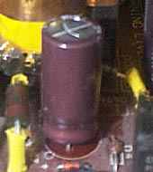
High voltage is another danger. Some capacitors can remain charged up to 350 volts even after the power is disconnected. These are usually (but not always) the physically large capacitors. You can damage yourself by discharging them with your fingers. You can damage the electronics if you trail the solder or Multicore desolder wick® across the circuit board and inadvertently connect a charged-up capacitor to a sensitive chip!
| 
| Repairing Sky Digital Receivers Not just a repair book! In fact not even a repair book! Common problems and cures listed - many of which you can fix yourself with only the remote control handset or a soldering iron. Plus lots of general repair information including how to recognise various components. Written in simple terms, this book also gives the home user valuable advice on how to prevent failure.
Read it NOW and save money in the future.
But, if the worst happens, read it anyway because it will still save you money. |
Give capacitors time to discharge before you carry out any work on equipment.
Sharp edges can give you a nasty cut. The cropped component wires beneath the circuit board are like thorns and the machine-cut edges of metal covers and base plates can be extremely sharp.
You are dangerous to the semiconductors! If you wear synthetic fibre clothing, walk across a nylon carpet or do anything to acquire a charge of static electricity, you can discharge several thousand volts into the circuit. Touch the equipment metalwork first, to equalise the voltages, before touching the printed circuit board.
High Quality Kit
The Multicore desolder wick® is almost pure copper with flux. I've chosen a wick with minimum flux content consistent with doing a good job. Flux is usually a resin that comes from a tree. Its function is to cover the joint and to exclude air so the solder can not oxidise. (For this reason, it is important to make the solder joint quickly before the flux is vapourised. Don't go back and "touch up" a solder joint to make it look prettier. You'll end up having to wick all the solder off it and start again! A good joint always looks shiny. If it's dull and grey it may be a "dry joint" that is not making good electrical contact). As you use up the Multicore desolder wick®, cut off and discard the solder section leaving just a short tinned part at the end. The Multicore desolder wick® oxidises fairly quickly in free air and becomes useless. It's best to keep it in an airtight bag and to exclude as much air as possible from the bag before sealing it.
The solder is the same as the stuff that I've used for the last fifteen years. It has just enough flux to guarantee a good solder joint without leaving a brown sticky mess.
The repair wire is called "Kynar" or (a different manufacturer) "Tefzel". It was originally developed for "wire wrapping" around square posts to make fast, reliable connections in telephone exchanges. It has a single strand of 0.25mm tinned copper wire which is insulated with "Teflon" heat-resistant plastic as used to coat frying pans. It is not cheap but it's the best stuff for our purpose. The insulation does not shrink back when the soldering iron tip is applied and it can be bent to follow a PCB track if necessary. Long runs should be secured near each end and middle with a blob of epoxy or silicone adhesive for safety sake. You don't want a snapped end to move across and touch a live mains connection! Obviously, the insulation is not good enough for high voltage (mains voltage) connections or the wire for carrying heavy current (more than an Amp).
Soldering iron
The kit will be useless to you unless you have an appropriate soldering iron. Mine was quite expensive. It's a 45 Watt "Weller" iron made by Cooper Tools and it has a 1.2mm tip that runs at approximately 430' Celcius. You can manage with something a lot cheaper but the secret is to have a small tip and as high a wattage as you can afford.
A 2mm tip is fine for general purpose work but you'll need a 1.2mm or 1mm tip for surface mount components. You also need much finer solder as supplied in this kit.
Side cutters
 Scissors won't do! I stock a low-cost pair of side cutters if you can't find anything suitable elsewhere. My own cost 25. The ones I sell are a tenth of that. Scissors won't do! I stock a low-cost pair of side cutters if you can't find anything suitable elsewhere. My own cost 25. The ones I sell are a tenth of that.
Go to KITS page Copyright ©1999 - 2012 SatCure
Version 1.2 updated on October 22, 2012
This file may be downloaded for private and personal use but NO part of it may be published in any form without the prior permission of the author. | |