|
|
|
|
|
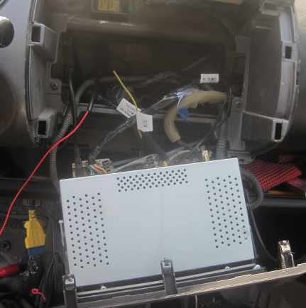
I had consulted the pages of wiring diagrams and decided that the only accessible ignition-controlled feed was the one to the rear screen and mirror heaters, which is on the radio panel. So out came the radio panel. I'm certainly glad that I had greased the clips previously! I poked a piece of black plastic tubing down the back of the compartment until it reached the clutch pedal. Then I fed a red wire through it. |
|
|
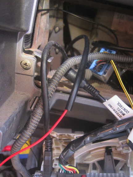
Here's a better photo of the black tube with red wire threaded through it. The tube is the type sold for garden watering systems. I tried silicone tube but it has a high coefficient of friction, making it very difficult to thread the red wire through. By the way, the wire doesn't need to be red; it was what I had available. Orange-black would be ideal but, as that's not readily available, use orange, yellow or red. |
|
|
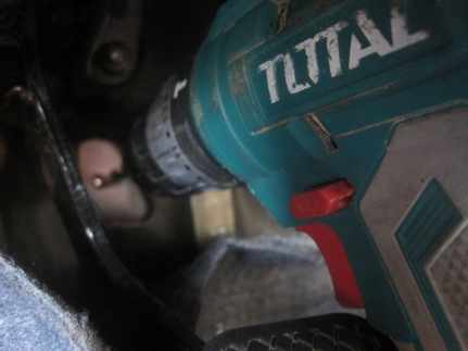
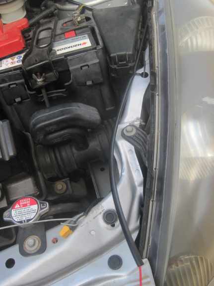
I removed a blank grommet in the firewall, behind the pedals, which revealed a second skin of metal. I drilled a 6 mm hole through that and checked in the engine compartment to see where it emerged. Perfect! |
|
|
I threaded the black tube and red wire through the hole and pressed Blu-Tack around the entry hole. It's probably better to seal it with silicone sealant. |
|
|
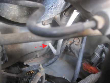
Under the bonnet I threaded another black tube over the red wire that emerged from the first tube that poked through the bulkhead and ran it to the front of the engine compartment, securing it with cable ties. |
|
|
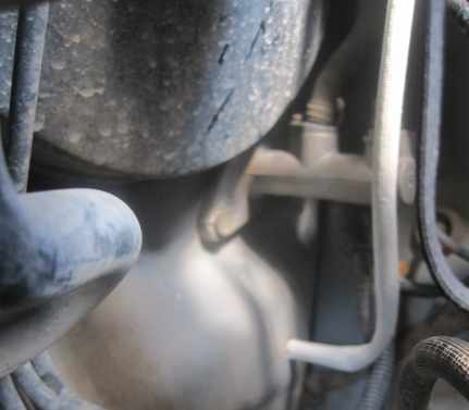
I joined the two black tubes with a length of fire resistant white sleeving that I threaded over them. |
|
|
This isn't essential but since I had it and the engine compartment becomes hot, I decided to use it. |
|
|
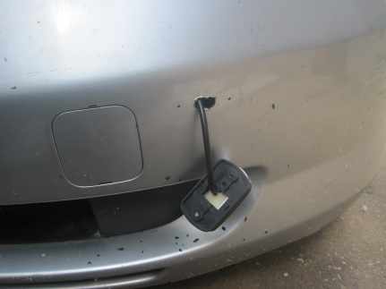
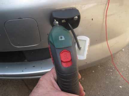
I drilled a hole in the front plastic skirt and ran the lamp cable through it, pulling it into the engine compartment with a length of steel wire. |
|
|
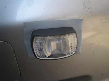
I drilled two holes for screws and fitted the lamp housing. |
|
|
I removed it, fitted a sheet of Blu-Tack behind and refitted it. I pressed the lamp into the housing and then trimmed off excess Blu-Tack. |
|
|
I repeated this at the other side of the car. I had already fitted yellow two-pin connectors to the lamp cables. |
|
|
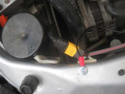
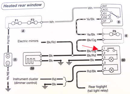
Back inside the car, I connected the red wire via a 3 Amp fuse to the ignition feed that powers the rear screen heater switch. I soldered it; not recommended but more reliable than Insulation Displacement Connectors (IDCs). I melted glue over the joint to insulate it. See wiring diagram, below. So, now I don't need to drive with sidelights on. |
|
|
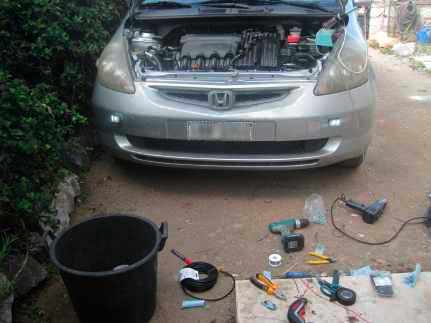
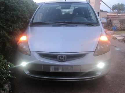
Comparison of the standard sidelights (very orange) and the new daytime lights, which stay on at night, too. I'm happy with the brightness and colour. I hope they are reliable. I'm tempted to replace the sidelights with white LED bulbs but accessibility is limited and I can't imagine that LED bulbs would last 22 years as the standard filament bulbs have! |
|
|
The live feed is taken from the black + orange wire that goes to the rear-screen heater switch. I found this to be the only accessible point that provides a 12 volt feed when the ignition is switched on. An easier point might be the cigarette lighter but this is also live when the ignition switch is in the accessory position and I didn't want that. |
|
|
I fitted an in-line 3 Amp fuse as close to the Bk/Og connection point as I could make it. This protects the wire from catching fire if a short circuit occurs in the new wiring. Fuse F9 provides additional protection but is rated higher at (I think) 20 Amps. |
|
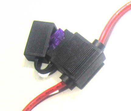
Initially I had planned to connect the new wire behind fuse F9 but I found it impossible to access. You could, of course, bodge it by using the blades from a melted fuse. Connect a fuseholder, as in the photo above, across the blades of the melted fuse. Put the original fuse into the fuseholder. Plug the melted fuse into position F9. Solder the new wire for your lights to one of the wires on the fuseholder and insert a 3 Amp fuse into the new wire, close to the fuseholder. So you end up with two dangling fuseholders. But it might be possible to do it neatly.
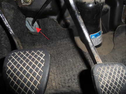
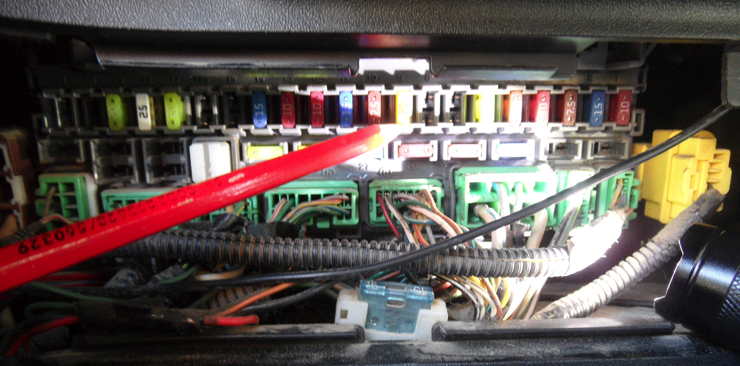
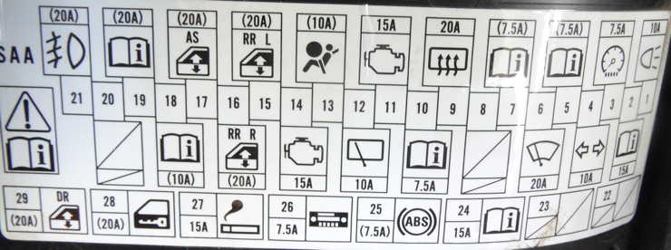
Yellow Fuse F9 indicated by pencil point. Each fuse has a number moulded into the plastic above it. I think that it would look messy but it might be easier than trying to remove the radio panel, which will be brittle with age. I was lucky in that I'd just installed a new radio head unit complete with new central panel, so removal wasn't difficult.
The somewhat confusing fusebox label. |
|
|
|
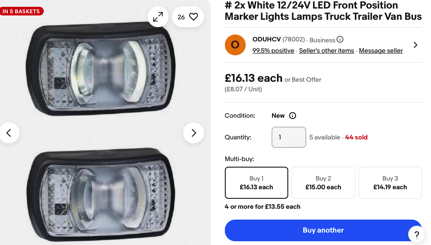
The lamps were ordered via eBay: https://www.ebay.co.uk/itm/185614178575 (I have no connection with the seller.) The lamps are not quite as bright as I would like but they are OK. Please check the car vehicle lighting regulations for your area to ensure that they are legal to use. Check with your local car test centre. |